
07 Jan Creating a Cleaner World through Radio Frequency Systems
RF ceramic substrate drying technology is being implemented around the globe to address increasing automotive regulations.
By Timothy D. Clark
President and CEO, Radio Frequency Co., Inc.
Radio frequency (RF) heating and drying systems were first developed in the early 1940s and have been used by the ceramic and glass fiber industries for over 50 years. Specialty cellular ceramic structures, such as extruded automotive catalytic converter substrates, cast ceramic particulate filters for metal castings, and glass yarn roving packages and forming cakes, continue to be dried in today’s state-of-the-art RF drying systems.
However, the drying of cellular ceramic extrusions represents a large global market for RF dryers because they offer the most practical way to dry these products quickly and uniformly, eliminating both the surface checking and dimensional quality problems associated with other drying methods such as microwave technology. Due to increased worldwide legislation for the use of catalytic converters for gasoline combustion engines and diesel particulate filters (DPFs) for diesel engines, RF ceramic substrate drying technology is being implemented around the globe at an accelerated pace to meet the new demands for higher production rates, part strength, and dimensional quality.
Principal of Operation
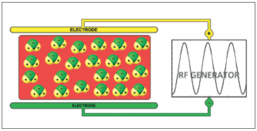
In an RF drying system, the RF generator creates an alternating electric field between two electrodes. The unique structure of the polar water molecule (H2O) is the basis for the thermal response of water when subjected to an alternating RF energy field.
As Anne Marie Helmenstine writes, “A water molecule is polar because of the difference in electronegativity between hydrogen and oxygen atoms. The highly electronegative oxygen atom attracts electrons of negative charge to it, making the region around the oxygen more negative than the areas around the two hydrogen atoms. Therefore, the hydrogen side of the molecule is relatively positive to the negative oxygen side.”
As the ceramic extrusions are conveyed between the electrodes, the alternating energy causes the polar water molecules to continuously reorient themselves to face opposite poles, much like the way magnets move in an alternating magnetic field. The friction of this movement causes the water in the material to rapidly heat throughout its entire mass. An important distinction of RF heating is the superior depth of penetration, as well as the uniformity of heating throughout the extrusion. At the higher frequencies applied by microwave systems, these critical factors become difficult to control and may result in non-uniform drying and poor dimensional control.
Another process advantage of RF equipment is in output power control. In high-power RF systems, the source and the load are part of the same circuit. Water molecules within the load have an electrical “capacitive” value required to “tune” the circuit for the optimal drying efficiencies. Therefore, when there is more water, the RF system will automatically deliver more drying energy. Conversely, when the product has fewer water molecules, the system automatically delivers less drying energy. This automatic power regulation requires no feedback circuit and is completely passive, which protects the load from overheating and also saves energy at times when the product stream is interrupted.
Frequency Selection
Field uniformity/penetration considerations for microwave processes can be explained as follows: Dealing with spatial non-uniformities in microwave processes has been an essential part of microwave engineering practice. These non-uniformities can be of particular interest due to the fact that the correct temperature throughout the whole mass may be critical to the effectiveness of the process with respect to strength and dimensional tolerance.
The microwave heating process suffers from two distinct forms of non-uniformity. The first is the fundamental “standing wave” effect. This is a repeated pattern of field intensity variation within a microwave applicator which, for the most part, follows a half-sine pattern. In a distance of one-quarter of the operating wavelength, the field intensity can change from a maximum to zero, or in a one-tenth of a wavelength, the intensity can change by 60%. Uniformity considerations can also play a role in the choice of frequency. The lower the frequency, the larger is the uniform volume.
-
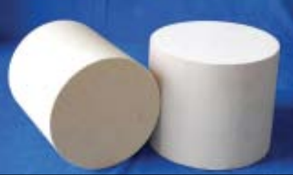
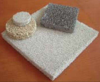
Diesel particulate extrusions. -
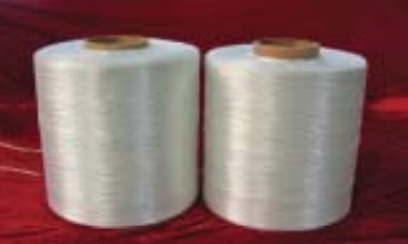
Typical glass package dried without migration of solids.
The second type of non-uniformity is the penetration depth problem. The microwave fields attenuate within the bulk of conductive materials and materials with high dielectric loss. This is particularly troublesome for larger scale processes. Both types of non-uniformities described above are frequency dependent and become less severe as frequency is lowered.
Figure 1 depicts an RF drying system with product between the electrodes. Polar water molecules within the product are represented by the spheres with + and – signs. Because water is far more receptive than other materials found in glass or ceramic, it is preferentially heated and evaporated in situ.
As the product dries out, it becomes increasing less receptive to RF heating, which provides a valuable safeguard against overheating and an automatic means of power regulation/conservation. This method of drying is therefore ideal for applications where uniformity of product dryness is an important requirement. The more difficult an item is to dry with convection heating, the more likely it is to be a good candidate for RF drying.
Materials with poor heat transfer characteristics, including ceramic and glass fibers, have traditionally been problematic when it comes to heating and drying. Radio Frequency heats all parts of the product mass simultaneously and evaporates the water in situ at relatively low temperatures, usually not exceeding 200°F. Since water moves through the product in the form of a gas rather than by capillary action, migration of solids is avoided. Warping, surface discoloration and surface cracks associated with conventional drying methods are also avoided.
Other Industrial Applications
RF systems have provided the means for drying several types of ceramic filters used by metal casting foundries. These filters are produced by firing parts made of plastic foam impregnated with ceramic slurry. After impregnation, the blocks are dried by RF, which has proven superior to conventional and microwave drying. The principal product applications for RF drying in the fiberglass industry are chopped strand, roving packages and forming cakes. RF dryers can uniformly reduce the moisture in these products to within a fraction of a percent of the desired level without overheating organic yarn coatings or, in the case of roving packages and forming cakes, without causing migration of solid components in the yarn treatments. In the ceramic and glass industries, the installed base of radio frequency dryers in the U.S. exceeds 3 MW of output power. This capacity is sufficient to evaporate 3,750 tons of water/hour, which is testimony to the importance of this drying method.
RF Drying Benefits
RF drying offers multiple benefits, including precise control of moisture content and uniformity, reduction/ elimination of surface cracks, and energy savings. In ceramic production, the primary cost driver is product yield. RF drying increases product yield because of the uniform level of dryness and dimensional tolerances throughout the product prior to the firing process. The moisture leveling phenomenon of RF drying occurs within each item being dried, as well as the entire product stream.
Surface cracks are caused by the stresses of uneven shrinkage during the drying process and are virtually eliminated by RF drying. This is achieved by the RF dryer’s even heating throughout the product, which maintains moisture and temperature uniformity from the center to the surface during the drying process. Other factors may contribute to surface cracks; however, the control of temperature and moisture uniformity achieved by RF drying has been the most significant in solving this production challenge.
In modern RF drying systems, careful attention is also paid to the control of temperature and humidity of the drying chambers throughout the drying process to match the conditions to that of the ware at all stages. This eliminates the potential for surface “shock”, which can occur if there is a thermal or moisture gradient between the substrates and the external environment.
RF dryers automatically adjust power output proportionately to the moisture of the incoming load. Unlike microwave systems, there is no need for an energy-wasting “dummy load” to prevent excess energy from being reflected back to the magnetron. In addition, since heating begins instantaneously throughout the product, the dwell time in an RF dryer is far less than in a conventional dryer. This translates into significant savings in floor space.
RF drying turns water into gaseous water vapor within the material being dried. Conventional drying methods require the water to move to the surface by capillary action, which often causes the undesirable migration of solids in suspension. This can be extremely important in the drying of many types of coated glass yarn packages and forming cakes, where the solids content needs to be uniform from head to tail.
The Importance of Frequency
The radio frequencies reserved for industrial use by the FCC are 13.56 MHz -+.05”/”, 27.72 MHz +.60”/”, and 40.68 MHz -+.05.”/”. It is important that the frequency remains within tolerance or be attenuated so as not to interfere with radio communications.
Earlier generations of RF dryers operate at 10-27 MHz. At these lower frequencies, 20-60% higher voltages must be applied to the product than if the equipment is operated at 40 MHz. These higher voltages often result in arcing, which can damage the product. The past use of lower frequency systems often resulted in the rejection of product applications where extremely low moisture levels were required and arcing problems caused the application to fail.
Modern design techniques produce RF dryers that operate at an internationally accepted frequency of 40 MHz and successfully handle drying applications once thought to be inappropriate because of arcing problems. An RF dryer operating at 40 MHz can do the same work as a 27-MHz or 13-MHz dryer, but at 20% or 40% lower voltage, respectively. At this frequency, all of the advantages of RF heating are available to producers of catalytic converters, DPFs and other products, without the arcing issues associated with older, lower frequency RF drying systems.
Greater control of all process parameters, including ambient humidity, temperature, and automatic loading and unloading, is employed to maximize product quality and production yield. Advanced designs have increased energy efficiencies; these include the utilization of generator cooling water to preheat process air, which serves to enhance the environmental sustainability goals of modern equipment designers.
Application Evaluation
The evaluation of an RF drying application usually begins with a feasibility study in the dryer manufacturer’s laboratory. Receptivity, dwell time, and power requirements are determined and economic factors investigated. If a product qualifies in a feasibility test, a further scale-up test can also be performed with a pilot line-sized leased system at the customer’s plant.
A complete thermal analysis can be conducted with the use of fiber optic temperature probes, which can be placed at various locations within the load and observed and recorded during the test. These probes are unaffected by the RF environment such that dynamic feedback can be provided throughout the test. At the same time, other factors such as power output, ambient conditions and exposure time can also be plotted throughout the test so that all scientific scale-up factors are immediately available for review.
Sorry, the comment form is closed at this time.